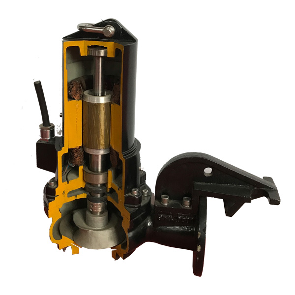
The hydraulic loss of the centrifugal pump has impact loss, vortex loss and friction loss along the path.
First, the impact loss
Each pump has its own design flow. When the consumption is under the design flow condition, the flow at the inlet enters the impeller along the blade, so no impact with the blade occurs, and the outlet flow does not occur. The impact of the pump casing is then more efficient. However, when the flow rate deviates from the design condition, the direction of the liquid flow deviates from the direction of the blade, causing an impact.
Second, the vortex loss
In the water pump, the flow cross section is a very complicated spatial section. When the liquid passes here, the flow rate is too small and the direction is constantly changed, so that vortex loss is inevitably generated. In addition, when the overcurrent surface has sharp corners, burrs, and dead water, the vortex loss is also increased.
Third, the friction loss along the way
Due to the roughness of the over-flow surface of the pump and the viscosity of the liquid, the frictional resistance loss occurs when the liquid swims. The size of the loss is expressed by the following formula;
Hm=AQ2 where A is the coefficient.
Painted on the coordinates, it is a parabola with the origin as its apex.
In the hydraulic loss of each part, the hydraulic loss in the impeller is the largest, accounting for about half of the total black and white loss; secondly, the hydraulic loss at the turn of the vane, accounting for about 1/4 of the total hydraulic loss, and the remaining 1/ 4 Hydraulic loss, loss in the impeller to the guide vane, the guide vane diffusion part, the anti-guide vane to the impeller inlet and other parts.
In order to reduce the hydraulic loss of the pump, the cross-section of the flow should be changed gently and the speed should be reasonable. And choose the appropriate impeller, vane type and entrance and exit placement angle. In addition, the surface finish of the overcurrent components should be increased.

